Aging Like Fine Water: Middleborough’s Historic Plant Gets a 21st-Century Makeover
Articles
Aging Like Fine Water: Middleborough’s Historic Plant Gets a 21st-Century Makeover
December 20, 2025
Allie Goldberg, PE, Weston & Sampson, Reading, MA
The Town of Middleborough, Massachusetts, is replacing its East Grove Street Water Treatment Plant (WTP), a historically significant facility that has served the community since 1913. Originally designed to address iron contamination through a pioneering deferrization process, the plant has been updated over the years but now faces limitations due to aging infrastructure and the presence of per- and polyfluoroalkyl substances (PFAS) in its drinking water. This project aims to modernize the treatment process while preserving the legacy of the original 1885 pump house.
The new facility will utilize advanced filtration technologies, including biological filtration for iron and manganese removal and granular activated carbon (GAC) for PFAS treatment. Efforts to protect the site’s historical integrity include the restoration of the pump house and careful consideration of floodplain risks. The design balances the preservation of a key historical asset with the need for a resilient, efficient water treatment system, ensuring long-term operational success and compliance with modern environmental standards. The project is funded in part by state revolving fund (SRF) financing and reflects the town’s commitment to maintaining safe and sustainable water infrastructure for its residents.
Background
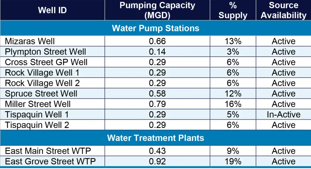
Middleborough, Massachusetts, located about 40 miles south of Boston, serves a population of over 24,000 residents. The town sources its municipal drinking water from 13 groundwater wells, with about 75% of its water supply distributed through nine pump stations across the town. These pump stations include chemical treatment for pH adjustment and chlorination before delivering water into the distribution system. The town also operates two water treatment plants: East Main Street WTP and East Grove Street WTP. The East Main Street plant is supplied by multiple wells, while the East Grove Street plant receives water from a single well. A detailed summary of water sources and treatment facilities is provided in Table 1.
TABLE 1. Water Supply Sources and Treatment Facilities
Historical Significance of the East Grove Street WTP
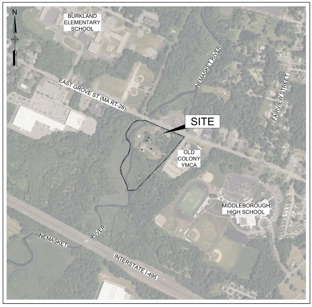
FIGURE 1. The 55 East Grove Street site
The East Grove Street WTP at 55 East Grove Street in Middleborough (Figure 1) supplies nearly 10% of the town’s drinking water. The history of the East Grove Street plant is deeply rooted in early 20th century water treatment innovations. The original pump house and the 22-foot-diameter dug well were constructed in 1885 and are still part of the operational facility. The dug well features a brick lining, starting approximately three feet above the well floor, with an annular strip of dry-stone masonry that allows water to percolate.
In 1913, Robert Spurr Weston, a pioneer in the field of water supply engineering, conducted a series of experiments for iron removal in drinking water for the towns of Middleborough, Cohasset, and Brookline. Weston’s work focused on oxidation and filtration processes to improve the quality of water and to remove iron efficiently. His studies demonstrated that the process was effective in removing iron, leading to the development of the East Grove Deferrization Plant—one of the earliest water treatment plants in the U.S. specifically designed to remove iron from drinking water.
Weston’s experiments and the resulting plant design were documented in the New England Water Works Association Journal (Volume XXVIII, 1914). The plant (Figure 2) was built in 1913 at a cost of approximately $18,000 and included:
Steam turbine-driven centrifugal pump: The original plant featured a centrifugal pump driven by a steam turbine, capable of pumping 1 million gallons per day (MGD) of raw water.
Coke aerator: After the water was pumped from the 1885 pump house, it was directed through a coke aerator to facilitate the oxidation of iron before passing through the stilling basin.
Slow sand filtration: After aeration, the water flowed into gravity-fed slow sand filters, which were used to remove any remaining particulate matter and iron precipitates.
Clearwell storage: Finally, the filtered water was stored in a clearwell, where it could be held before distribution to the town.
This historic facility remains in operation today with only minor modifications, such as upgrades to maintain growing demands. In 1921, the steam pump was replaced with an electric pump and in 1939, the plant was expanded to include an additional slow sand filter and a second clearwell.
The building and associated treatment infrastructure are considered significant from a historical perspective and were listed on the National Register of Historic Places due to their importance in the development of water treatment technology.
FIGURE 3. WTP daily records from 1906.
Although the facility has served the town for over a century, the original plant is now unable to meet the full authorized withdrawal capacity of 0.43 MGD under the Water Management Act. The plant’s capacity has been limited by treatment equipment including the pumping system, electrical components, and the slow sand filters, all of which are nearing the end of their useful lives.
PFAS Testing and Response
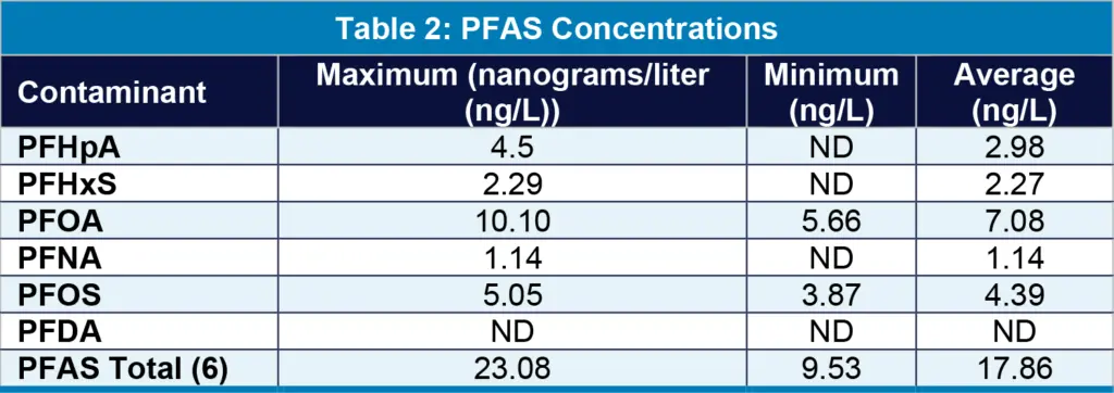
In the summer of 2020, the town began testing for PFAS and detected elevated levels in the raw water from the dug well that supplies the East Grove Street WTP. Table 2 summarizes PFAS concentrations collected between January 2023 and May 2023.
TABLE 2. PFAS Concentrations
With the East Grove Street WTP facing reduced capacity due to aging infrastructure and contamination from PFAS, the town retained a consultant to evaluate upgrade alternatives for this historically significant facility. Despite its age, the plant remains a critical component of the town’s drinking water system.
Following a preliminary assessment, it was determined that retrofitting the existing facility, which would require the full replacement of failing equipment and the addition of PFAS treatment, would be comparable in cost, if not more expensive, than constructing a new water treatment plant on the same site. Consequently, the town chose to pursue the design of a new facility while honoring the legacy of the original plant.
Project Objectives
The replacement of the East Grove Street WTP focused on improving water treatment capabilities while maintaining the legacy of the site. Key project objectives included:
Reinvesting in the existing dug well as a dependable water source.
Constructing a new, above-ground water treatment plant on the same property to improve treatment capacity and access.
Providing treatment for PFAS, iron, and manganese in the raw water supply.
Restoring the historic 1885 pump house while preserving its architectural and historical value.
Enhancing Department of Public Works (DPW) operations through:
Modernized and expanded administrative spaces.
A new vehicle storage garage to accommodate DPW vehicles and equipment.
Securing SRF financing to support the project
This forward-looking approach not only addresses immediate public health and infrastructure challenges but also reflects the town’s commitment to honoring its water supply heritage while investing in a sustainable future.
WTP Design
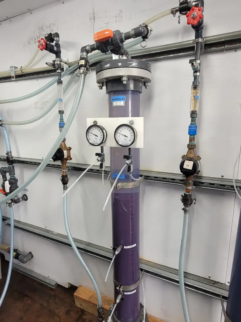
Figure 4: PFAS pilot testing.
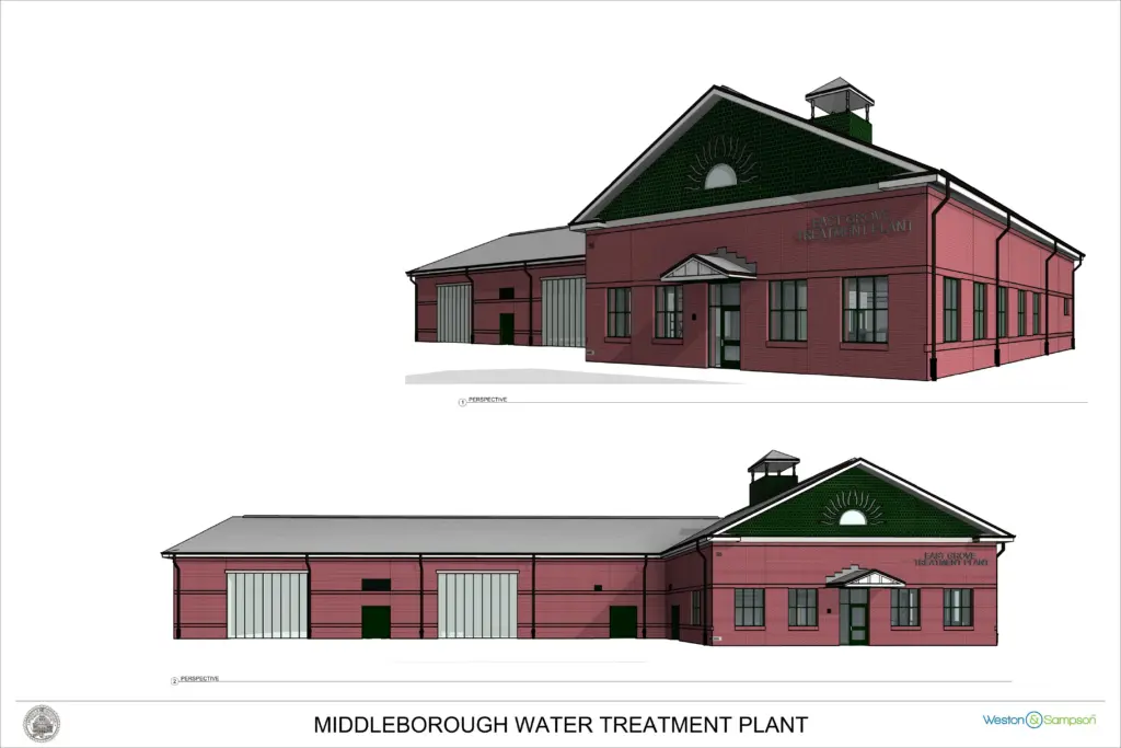
The new 9,500-square-foot East Grove Street WTP is designed to treat up to 500 gallons per minute (GPM) of groundwater for iron, manganese, and PFAS. The treatment process consists of biological filtration for iron and manganese removal, along with GAC filtration for PFAS removal. All treatment technologies proposed for the facility were successfully piloted on-site (Figure 4) to validate performance and optimize process design.
The facility was designed to serve a dual purpose. Approximately 50% of the building footprint is dedicated to water treatment operations while the remaining 50% of the building accommodates administrative functions and serves as the primary office for the Town of Middleborough Water Department.
Administrative spaces include:
A superintendent’s office
Open office areas for staff
Break rooms and support spaces for daily operations. This integrated facility layout supports both operational efficiency and staff comfort while ensuring the long-term viability of the town’s water infrastructure.
Site Considerations
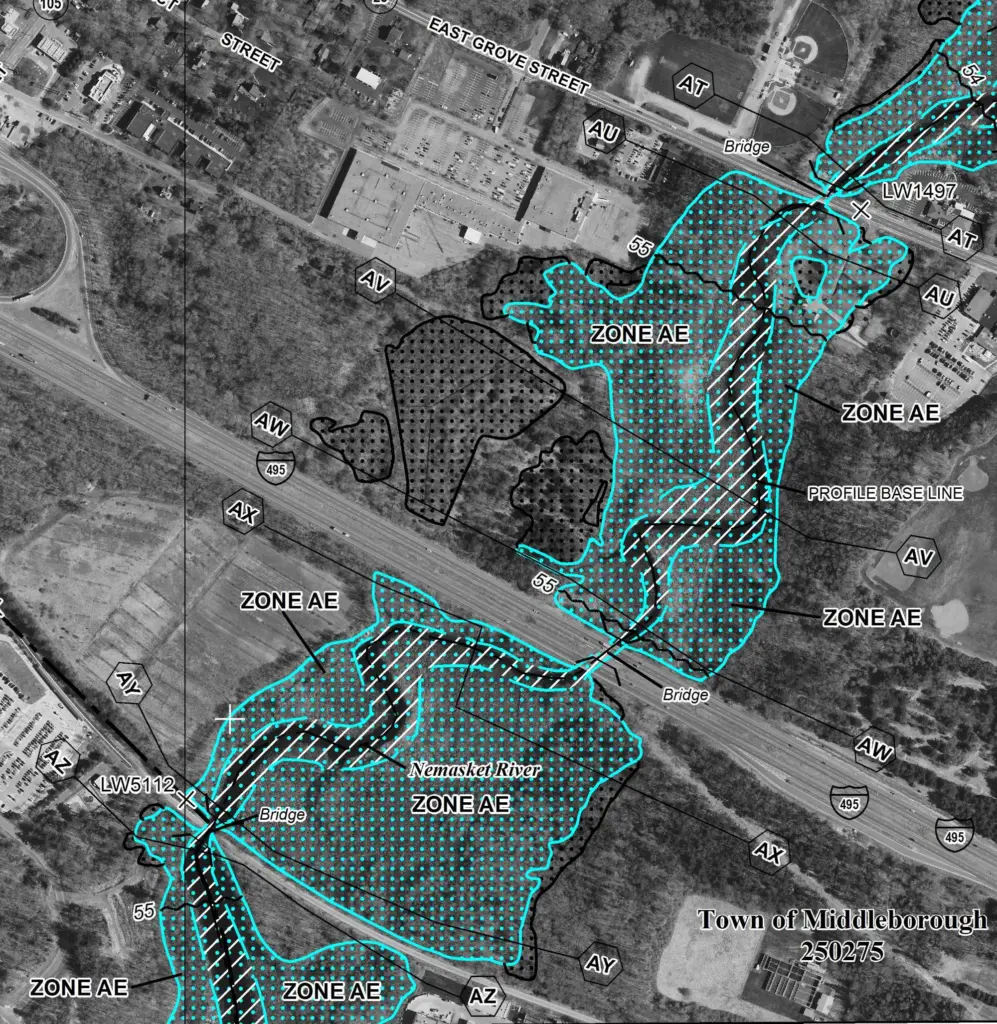
Figure 5: FEMA floodplains in the area of the East Grove Street WTP.
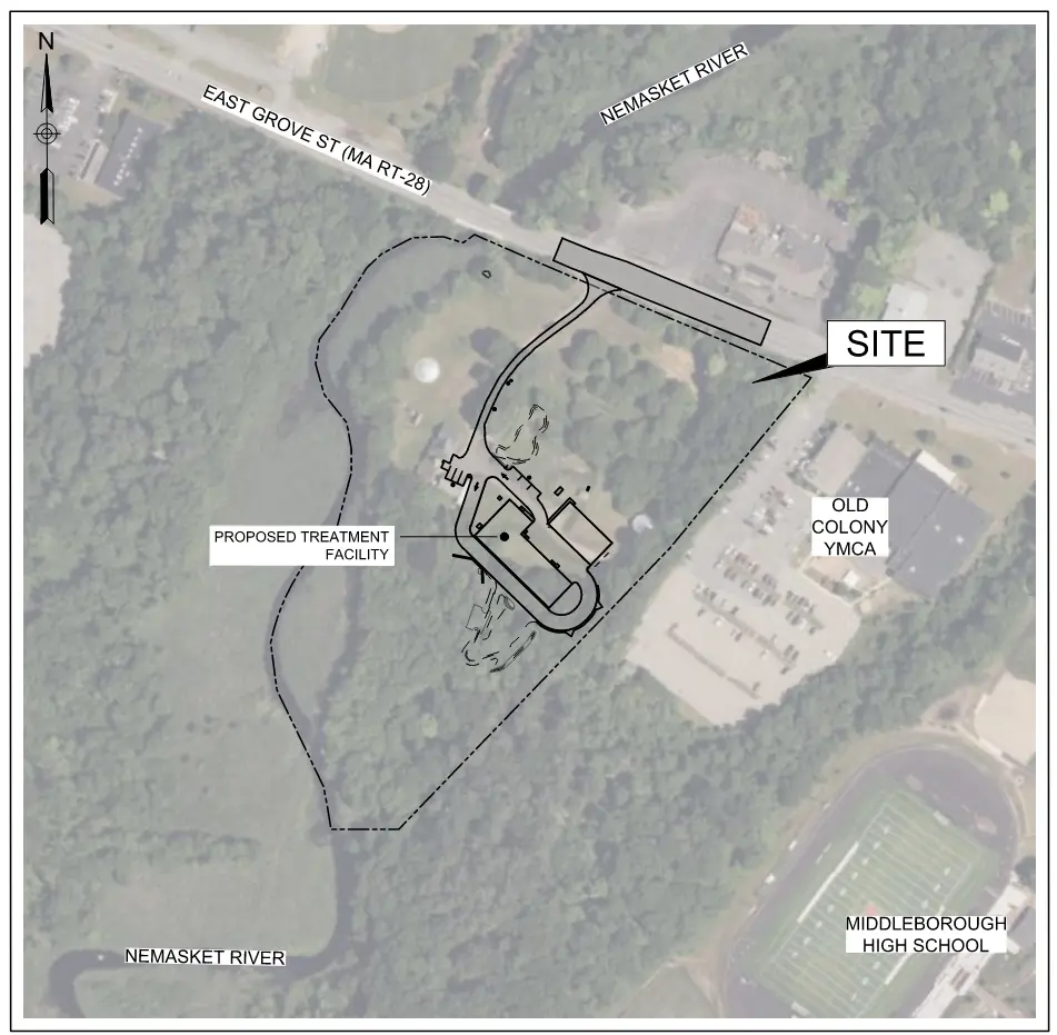
The site of the proposed replacement of the East Grove Street WTP is bounded by East Grove Street to the north, the Nemasket River and associated bordering vegetated wetlands to the west, and a YMCA facility to the east. The southern and northeastern portions of the property consist of undeveloped woodlands.
Although the site has been in use since the late 1800s, redeveloping and permitting new construction at this location presents several significant challenges. More than 50% of the 8-acre parcel lies within the FEMA-designated floodplain. Figure 5 illustrates the extent of flood risk on the property.
As the proposed water treatment facility constitutes critical infrastructure and is partially funded through the SRF, the design needed to comply with the Federal Flood Risk Management Standard (FFRMS). In response, the project team developed four conceptual site layouts to accommodate the new water treatment facility and vehicle storage garage. Each concept was evaluated to minimize impacts to environmentally and historically sensitive areas, including riverfront zones, floodplains, wetland buffers, and potential historic features, while ensuring continuity of plant operations.
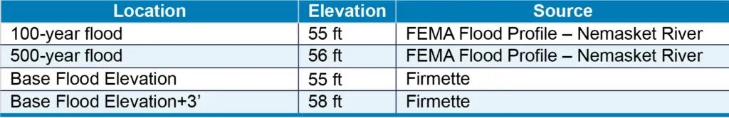
A primary design objective was to site the new facility outside the floodplain to the greatest extent feasible. Furthermore, all critical mechanical and electrical equipment must be located at least three feet above the base flood elevation, in accordance with FFRMS requirements. A summary of property-specific flood elevations is provided in Table 3.
TABLE 3. Project Components and Flood Elevations
To comply with the FFRMS, the site design incorporated strategic grade modifications to elevate key infrastructure above the required base flood elevations. In several areas of the site, existing grades were raised by approximately five feet to ensure sufficient elevation for flood resilience.
Because a portion of the site lies within the FEMA-designated flood zone, achieving the necessary elevation required placement of fill. To mitigate the impact of this fill within the floodplain, the project team incorporated compensatory flood storage in accordance with regulatory requirements.
The finished floor elevations for key structures within the selected site layout are summarized below:
In addition to elevation-based mitigation, the facility incorporates several passive and active flood protection measures, including:
Waterproofing: Exterior walls are treated with a waterproofing membrane and a protection board system to prevent water intrusion.
Structural Design: All structural elements are engineered to withstand hydrostatic pressure and the building is designed to resist buoyant forces under flood conditions.
Site Grading: Exterior site grading has been sloped away from the foundation to promote surface drainage and reduce the potential for localized flooding.
These design elements ensure that the new facility meets both regulatory requirements and long-term operational resilience goals in the face of increasing flood risks.
Historical and Archaeological Considerations
An important factor in selecting the final site layout was the need to minimize development within previously undisturbed portions of the property. By prioritizing areas that had already been developed, the design team was able to reduce the risk of impacting archaeologically or historically sensitive locations. The project site was identified as having high pre-colonial contact archaeological sensitivity, with only the wetlands and the immediate surroundings of the existing water treatment facilities classified as low sensitivity.
Given the site’s sensitivity, the project team engaged early and often with the Massachusetts Historical Commission (MHC). Upon selection of the preferred site layout, the MHC confirmed that several portions of the project area are considered archaeologically significant, particularly for Native American and early historical resources. Accordingly, the MHC requested that an intensive (locational) archaeological survey be undertaken to identify any potential significant archaeological deposits.
This survey followed the methodologies outlined in MHC’s Public Planning and Environmental Review: Archaeology and Historic Preservation (1979), as well as the Secretary of the Interior’s Standards and Guidelines for Archaeology and Historic Preservation. It also complied with Section 106 of the National Historic Preservation Act of 1966, as amended (36 CFR 800). The scope of the investigation included both archival research and onsite field surveys. Prior to the commencement of archaeological work, the project team formally notified local tribal representatives and provided an opportunity for input regarding the approach, focus areas, and cultural considerations of the survey.
The findings of the archaeological survey are confidential and were submitted to the MHC for review and approval. As a result of the survey, no modifications were necessary to our preferred conceptual site layout.
To further preserve the site’s integrity, the selected site layout required the new water treatment facility and vehicle storage building to be constructed above an existing underground treatment system. This approach allowed the project to avoid impacting undeveloped areas and facilitated the design of a phased construction strategy that enables the existing plant to remain in service throughout the duration of construction. Additional details on the construction phasing are provided in the following section.
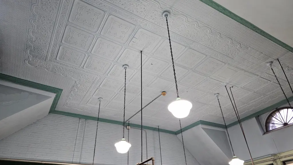
Figure 7: The decorative ceiling of the 1885 pump house.
Historic Building Restoration
An additional project goal was the restoration of historically significant aboveground structures. The centerpiece of this effort was the rehabilitation of the 1885 pump house (Figure 7), with work guided by The Secretary of the Interior’s Standards for the Treatment of Historic Properties, published by the National Park Service. Restoration measures include:
Replacing damaged slate roof shingles.
Installing new windows and doors to match the original design.
Repointing masonry joints and replacing deteriorated or missing bricks.
General repairs using materials and methods consistent with the building’s original construction.
The design team worked closely with both the MHC and the Middleborough Historical Commission throughout the restoration planning and design process.
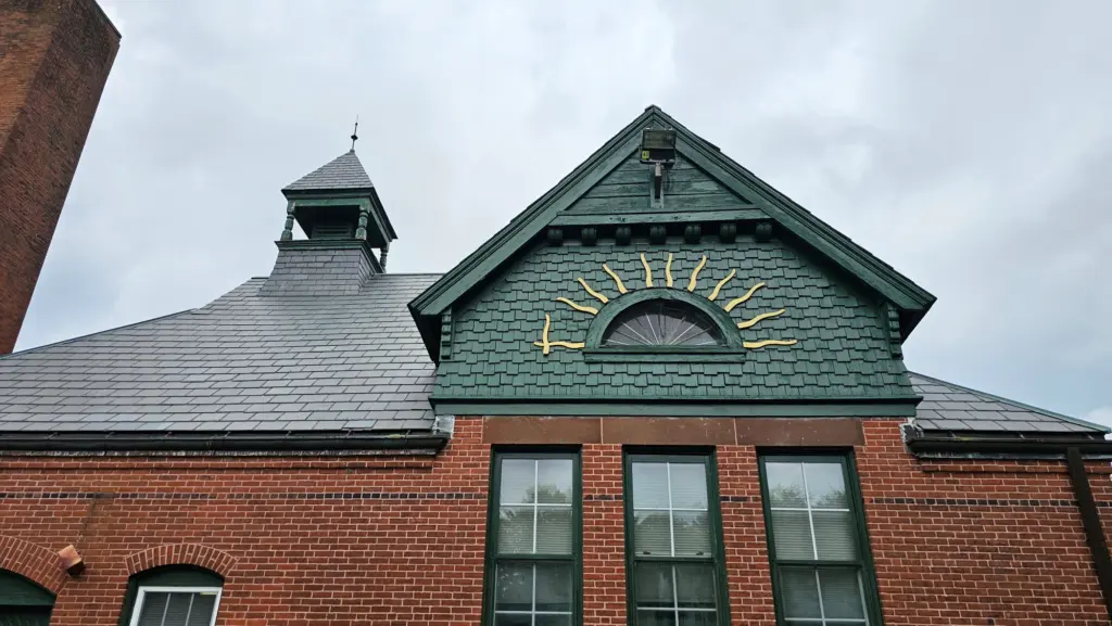
To ensure architectural continuity between old and new facilities, the new WTP was designed to reflect the aesthetic character of the historic pump house. Notably, architectural elements such as the sundial and cupola from the original structure (Figure 8) were incorporated into the design of the new facility.
Figure 8: The cupola and sundial on the 1885 pump house.
Keeping the Water Flowing During Construction
To ensure uninterrupted water service throughout the estimated 2.5-year construction period, the project will be executed in two phases. Phase I will focus on the construction of the new WTP. This phase will include the demolition of select existing underground infrastructure and the installation of temporary utility systems to maintain water service continuity. Phase II will involve the construction of a new vehicle storage facility, at which point the remaining treatment systems from the existing plant can be safely demolished and removed.
A Permitting Smorgasbord
Given the complex nature of the East Grove Street WTP replacement project, the permitting process proved to be a multifaceted and time-intensive task, requiring coordination across a wide range of agencies at the federal, state, and local levels. The age and historical significance of the existing facility, coupled with its location within sensitive environmental and archaeological areas, made securing the necessary approvals a critical component of the project’s timeline and success.
To ensure compliance with regulatory requirements and maintain eligibility for SRF funding, permitting efforts were initiated as early as possible. The project team engaged with numerous permitting agencies to navigate the complexities and ensure the development of the new facility aligned with all environmental and historical preservation standards. Below is a breakdown of the key permitting agencies.
U.S. Army Corp. of Engineers
Massachusetts Department of Environmental Protection (MassDEP)
Massachusetts Department of Transportation (MassDOT)
Massachusetts Historical Commission (MHC)
Middleborough Historical Commission
Middleborough Board of Selectman – Water Resource Protection District Special Permit (WRPD)
Middleborough Conversation Commission
Middleborough Building Department
Middleborough Zoning Board of Appeals (ZBA) – Special Permit
Summary
Navigating the permitting challenges for the replacement of the East Grove Street WTP required careful consideration of the site’s unique and sensitive conditions. The location, steeped in history and surrounded by floodplain areas and wetlands, presented significant regulatory hurdles. The site’s designation within the FEMA flood zone, coupled with its archaeological sensitivity, required extensive coordination with multiple permitting agencies, including the Massachusetts Historical Commission, U.S. Army Corps of Engineers, and the Massachusetts Department of Environmental Protection. These challenges were met through strategic planning, including elevation-based flood mitigation, compensatory flood storage, and a phased construction strategy that minimized disruptions to existing water service.
Looking ahead, the project underscores the importance of balancing historical preservation with the need for modern, resilient infrastructure. As the Town of Middleborough moves forward with this vital upgrade, the new facility will not only enhance water quality and capacity but also provide a model for integrating sustainable practices into historic sites. The lessons learned from the permitting process will help guide future infrastructure projects in similar sensitive environments, ensuring that the community can continue to enjoy a reliable and safe water supply while honoring its historical heritage.
The East Grove Street WTP replacement project is a vital step toward securing Middleborough’s water future while honoring the site’s significant historical legacy. Through careful planning, engineering, and collaboration with historical commissions, this project ensures that the town’s water infrastructure remains robust and resilient for generations to come.